Principle of operation
The heart of this motor controller is the PIC18F252. The circuit and its software allow control of the motor position under serial remote control (RS485) or under pre-programmed automatic control. The controlled motor when instructed to move, starts slowly and increases in speed to a preset maximum, then as it approaches the target position the speed reduces again till the target is attained.
Speed feedback is derived from the motor itself, i.e. no separated tacho generator. This is done by running the motor for 18ms then removing the supply for 2ms. After 1ms the back emf driving the flywheel current in the motor has died away and the generated emf, which is proportional to its speed, is measured. This cycle is run continuously. The speed being controlled by Pulse Width Modulation of the power supplied to the motor.
Positional feedback is acquired from pulses generated from an appropriate source as the motor and its gear chain turn. This is a standard part of a linear actuator. Also built into these actuators are end stop limit switches. These limit switches are in series with the motor and have a diode across them to enable retreat from the limit once reached and the switch opened. They do not however have a tell back that can be used for indicating to the software the limit is reached. During the calibration cycle the actuator is run from end to end and the position pulses counted so the processor knows its travel limits. This lack of tell backs is overcome by surmising the lack of positional pulses when the motor is being driven in a particular direction is because it has reached this limit switch, and of course the same for the other direction and other limit switch. This calibration cycle along with the serially supplied Max_Angle and Min_Angle values allows calculation of the position in degrees. It should be noted there is no adjustment made for the fact that it is a tangent bar so the positional accuracy in degrees is limited and dependent upon the angular movement and set up of the tangent bar.
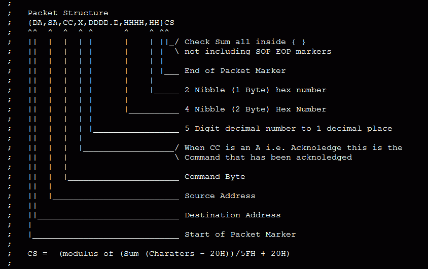
Serial Communications is multi drop addressable RS485 in a master slave configuration. The master interrogates the multiple slaves who only talk when spoken to. This eliminates the need for collision detection and greatly simplifies the software. The protocol involves a packet structure containing commands and data where appropriate and expected responses acknowledgments. Some of the commands are shown.
There are three modes of operation STOP stays stationary and ignors any commands to the contrary. COMAMAND this accepts commmand i/p and will move to any instructed position told to via serial port command then awaits further instructions. The third mode is TRACK (really predict) this point to a serries of pre-programmed poitions every 15 minutes.These are the directions the sun should be in for this time of day at this time of year. This data is precalculated and loaded in a table contained in the PIC18F252 program area. This data is accurate to about +/- 4 degrees at any time. The data is stored for 15 min intervals throughout the day and while the sun is above the horizon and throughout the year.
| |
Packet Structure

|
| Processor Commands |
Recieved |
Returned |
| Return Software Version |
{DA,SA,?},CS |
{DA,SA,A,?,S/W Version string}CS |
| Acknowledge Packet |
{DA,SA,'A','x'},CS |
No Action Taken |
| Set PWM1 Max,Ini,Inc,Min |
{DA,SA,'B',HHHH,HHHH,H,HHHH},CS |
{DA,SA,A,B},CS |
| Set PWM2 Max,Ini,Inc,Min |
{DA,SA,'C',HHHH,HHHH,H,HHHH},CS |
{DA,SA,A,C},CS |
| Set Time |
{DA,SA,'D',2008/01/01/7-16:50:59},CS |
{DA,SA,A,D},CS |
| Set TMR0_reload (Clk_Adjust) |
{DA,SA,'E',HHHH},CS |
{DA,SA,A,E},CS |
| Return Settings |
{DA,SA,'F'},CS |
{DA,SA,A,F,HHHH, HHHH, H, HHHH, HHHH, HHHH, H, HHHH, HH, HH, HH, HH, HH, HH, HHHH},CS. i.e.:- PWM1-Max, Init, Inc, Min, PWM2-Max, Init, Inc, Min, WDT_Count, POR_Count, BOR_Count, RX_HnT_OvrRun, Tx_HnT_OvrRun, Rx_WDF, RXSW_Failed, TMR0_Reload |
| Set New Unit Address |
{DA,SA,'G',HH},CS |
{DA,SA,A,G},CS (new Address change imediate) |
| |
|
|
| Unit Commands |
Recieved |
Returned |
| Return Unit settings |
{DA,SA,U,0},CS |
{DA,SA,A,U,0,DDDDD.D, DDDDD.D, DDDDD.D, DDDDD.D, HHHH, HHHH, HHHH, HHHH},CS. i.e.:- Max_Angle, Min_Angle, Stow_Angle, Park_Angle, M1_Speed-Tol_0, M1_Speed-Tol_1, M1_Speed-Tol_2, M1_Speed-Tol_3, Light_Level_Tol, Start_Light_level, Track_Timer_period, |
| Return Unit Status (Hex) |
{DA,SA,U,1},CS |
{DA,SA,A,U,1,HHHHHHHHHH, HHHHHHHHHH, HHHHHHHHHH, HHHH, HHHH, A,A},CS. i.e.:- M1_Max_Position, M1_Target_Position, M1_Position, Sun_Sensor_1, Sun_Sensor_2, M1_Fwd_Rev_Off (F/R/O), M1_Run_Trip(R/T) |
| Return Unit Status (Decimal) |
{DA,SA,U,3},CS |
{DA,SA,A,U,2,DDDDD.D, DDDDD.D, DDDDD.D, DDDDD.D, DDDDD,D, A, A, HH, HHHH, DDDDD.D},CS. i.e.:- M1_Positon(deg), Battery_Voltage, M1_Current, Sun_Sensor_1_Voltage, Sun_Sensor_2_Voltage, M1_Fwd_Rev_Off (F/R/O), M1_Run_Trip(R/T), M1_State, Minutes_Since_Time_set, M1_Feedback_Voltage, |
| |
|
|
| |
|
|
| |
|
|
| |
|
|
| |
|
|
| |
|
|
| |
|
|
Circuit Principle Blocks
- Circuit diagram
- D1 reverse polarity protection.
- U1, IC1, C4, C5, C10, C8, C23, C24 power supply and decoupling.
- R8, R1,R6 Power supply voltage monitoring.
- R4, ZD1, C7, R7 tacho feedback conditioning.
- IC3, R10, R11, R12 RS485 Communications transceiver.
-
|
