Mains Energy Monitor
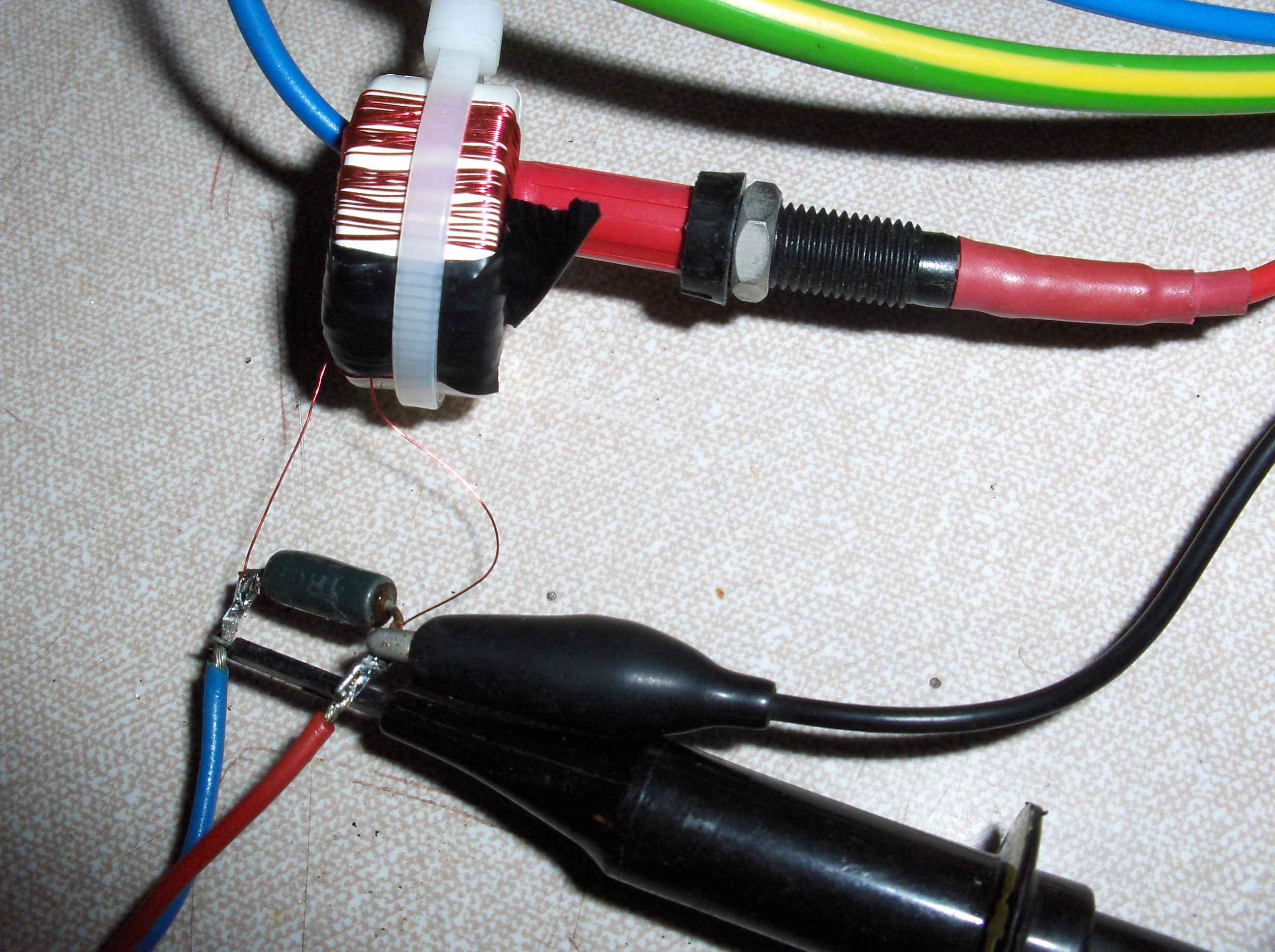
This project went through several iterations of trying a method and rejecting it. The first idea was to use a current transformer. (Like the rest of the world) I wound the transformer and tested it. designed a intrumentamp preamp for it. Wrote the software including the squareroot so i could do a proper RMS value of the current measured. I had intended to do a continuouse sample over a second add up the sum of the squares and do the square root (time consuming) in the next second while the new values for the new second were being collected. All this using a PIC18F252.
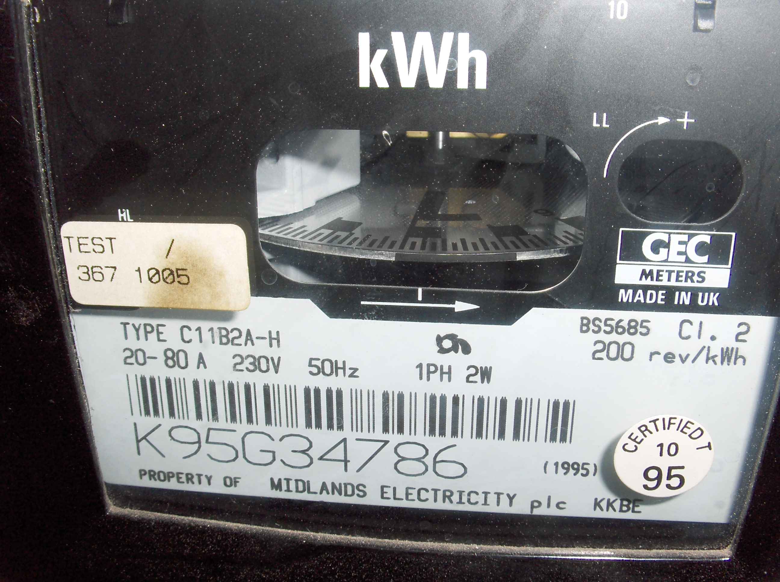
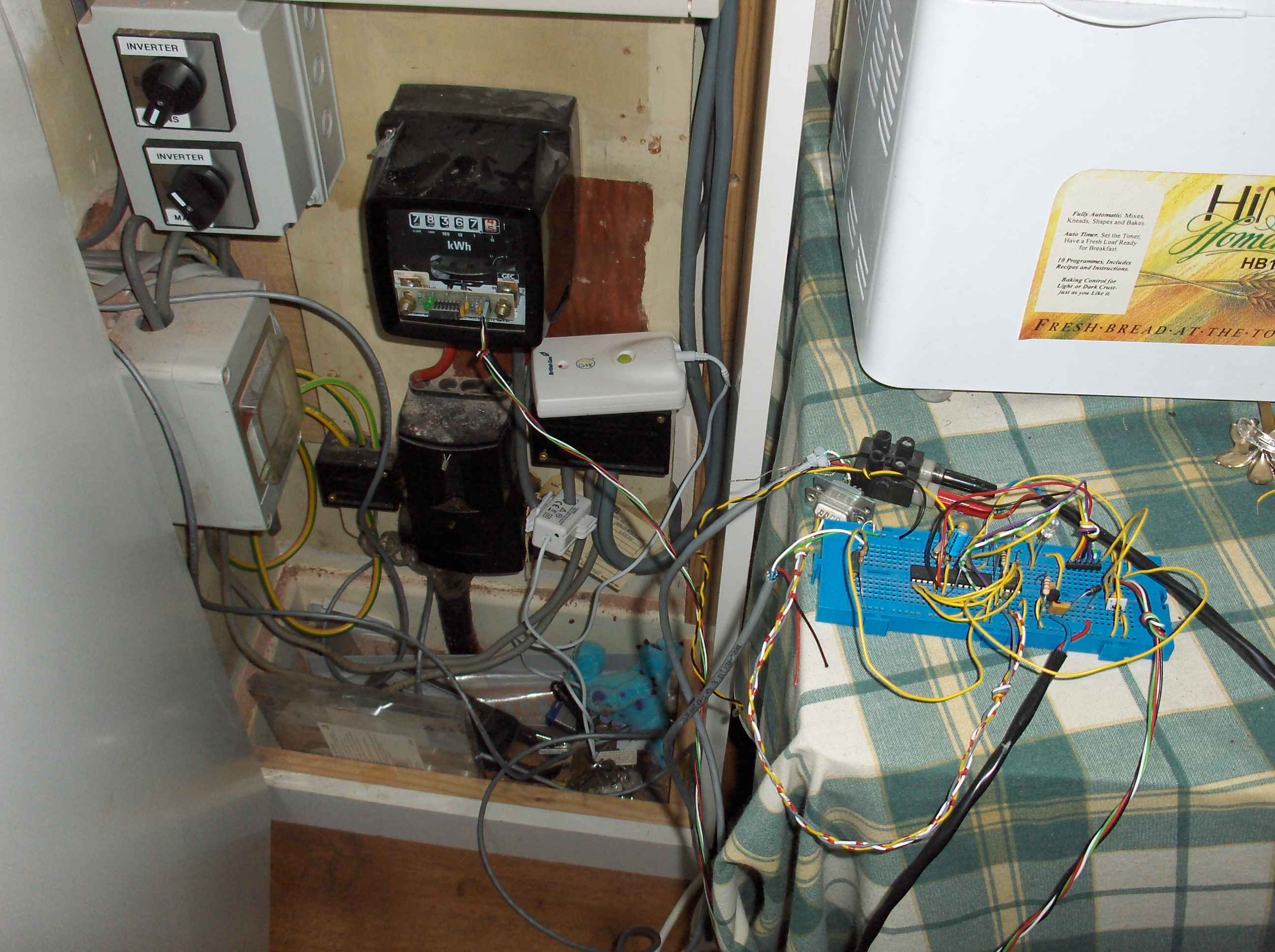
Alass the PIC18F252 was just not quick enough. And besides the data collected would NEVER be what the energy company was actually charging me for. So a new approach was required. I would Count The revolutions of the disc in the electric meter. If you look at the disk on it's edge it has a black section just before the transition from 0.9 to 1 revolution.
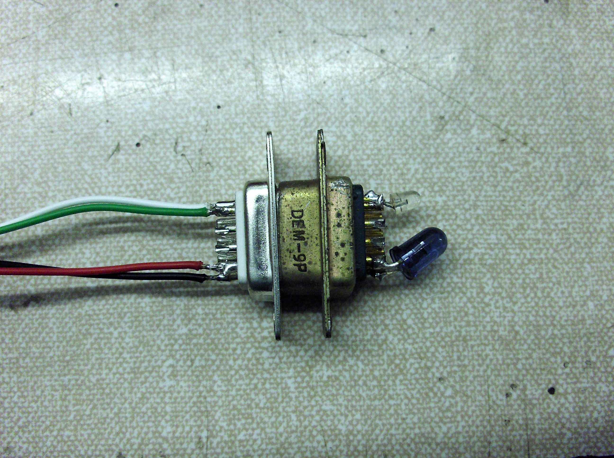
I tried a miniature sensor but found that becaus the tx and rx devices were so close together the light reflected back by the glass air transition. was so high that is swamped the light back from the disc. The Tx/Rx needed to be farther apart this was the first experiment solution. This spacing worked fine
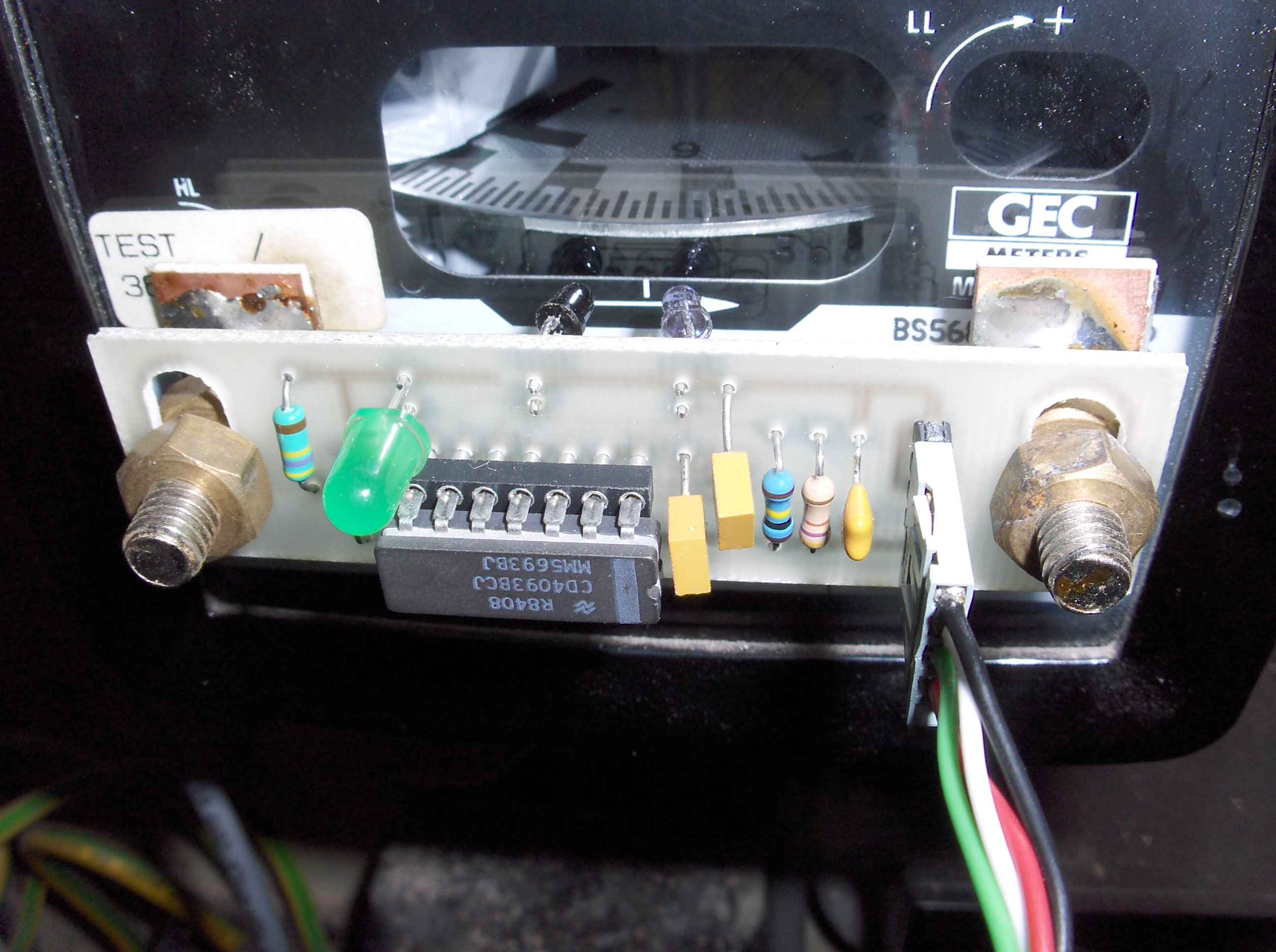
This is the protype of the signal conditioner from Opto Tx/Rx which is identical to the az motor feed back cct.
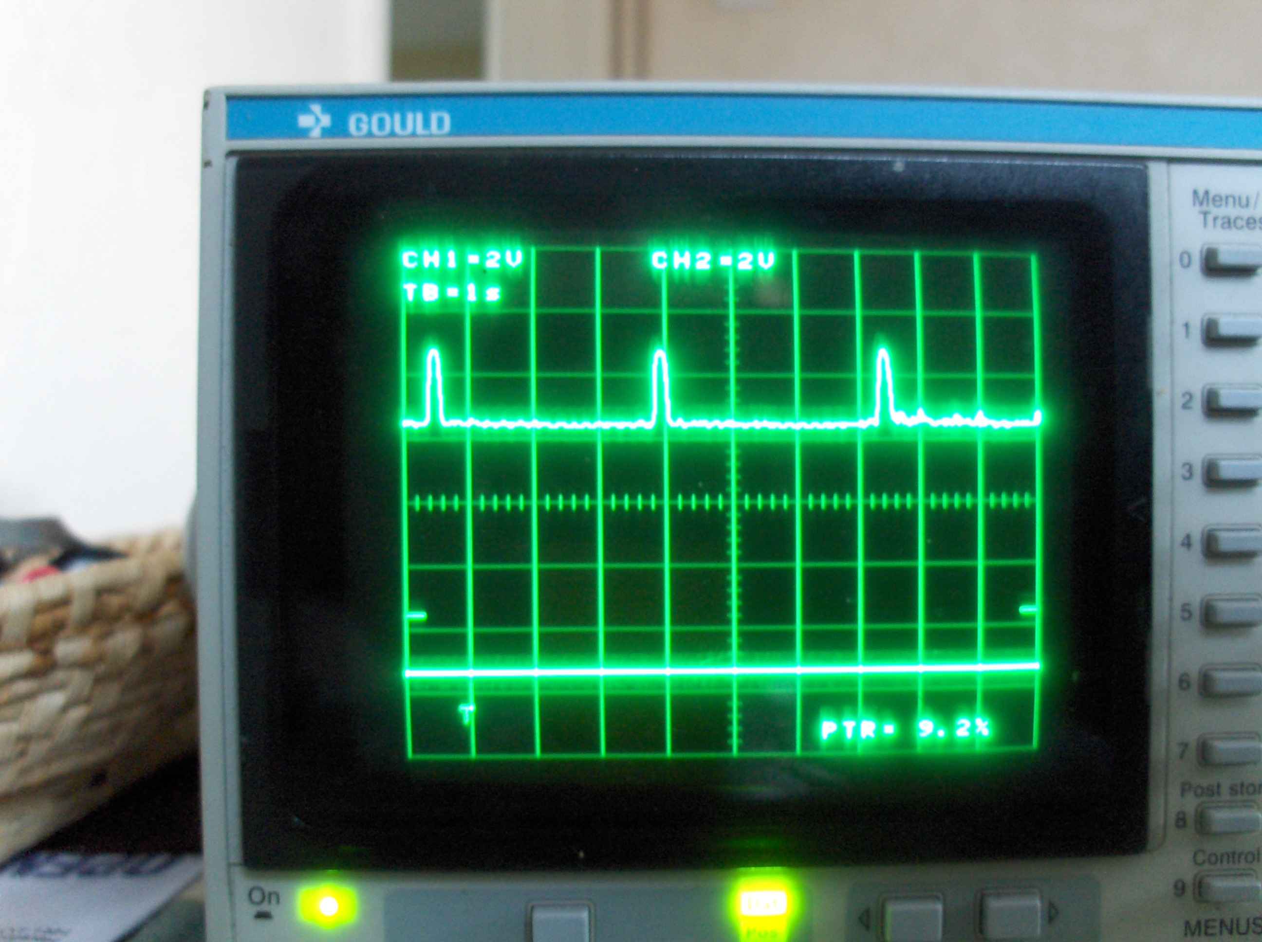
The pulse train from the actual Rx before conditioning.
The finished Opto sensor with integral adjustment fited to the electric meter.
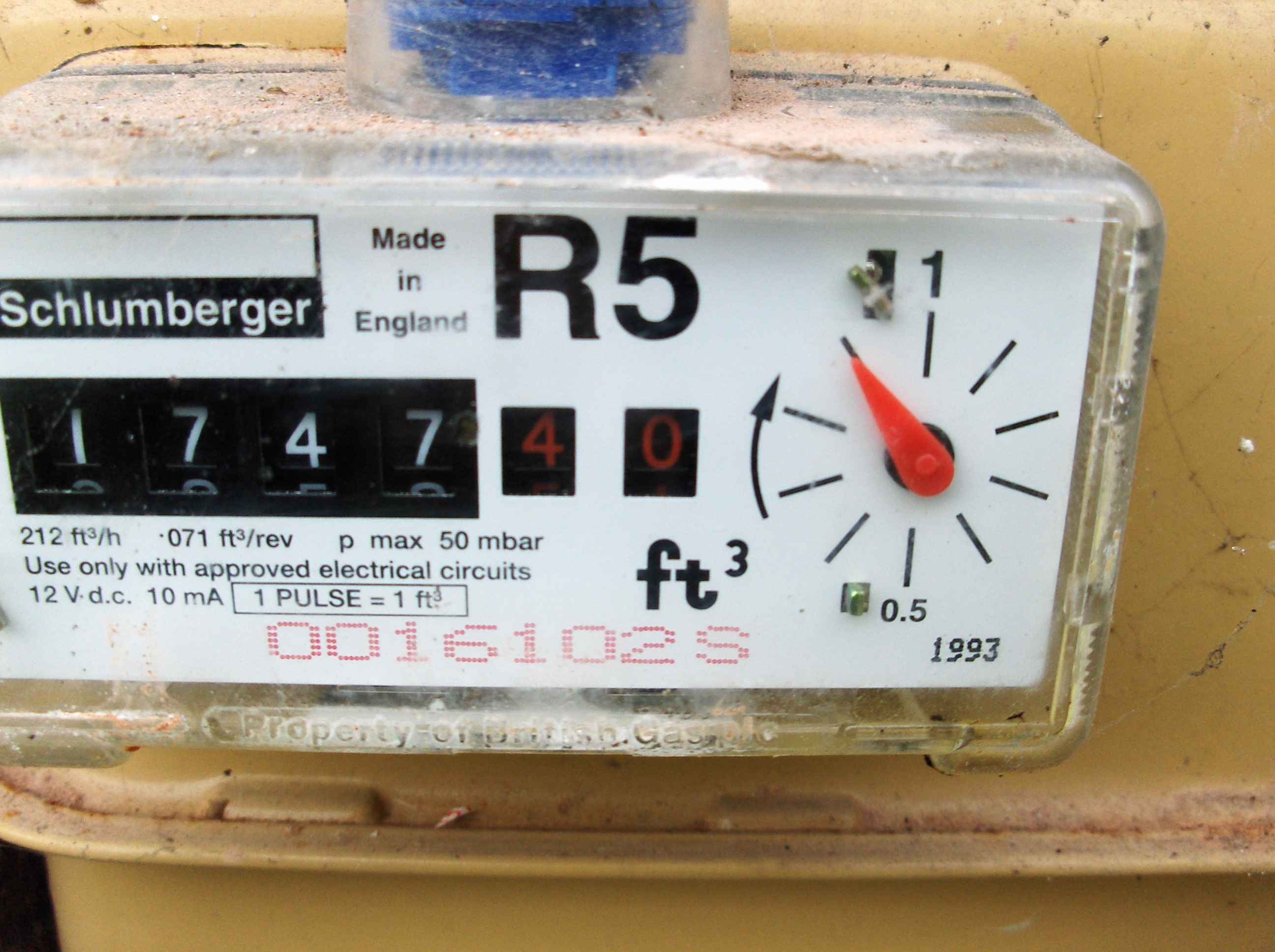
I also wanted to monitor the gas use and as you can see the gas meter has a built in set of contacts that permit this.The final cct is a 5V 1mA Opto Isolated connection to the meter giving a 2KV isolation from any electrical cct and the gas meter.
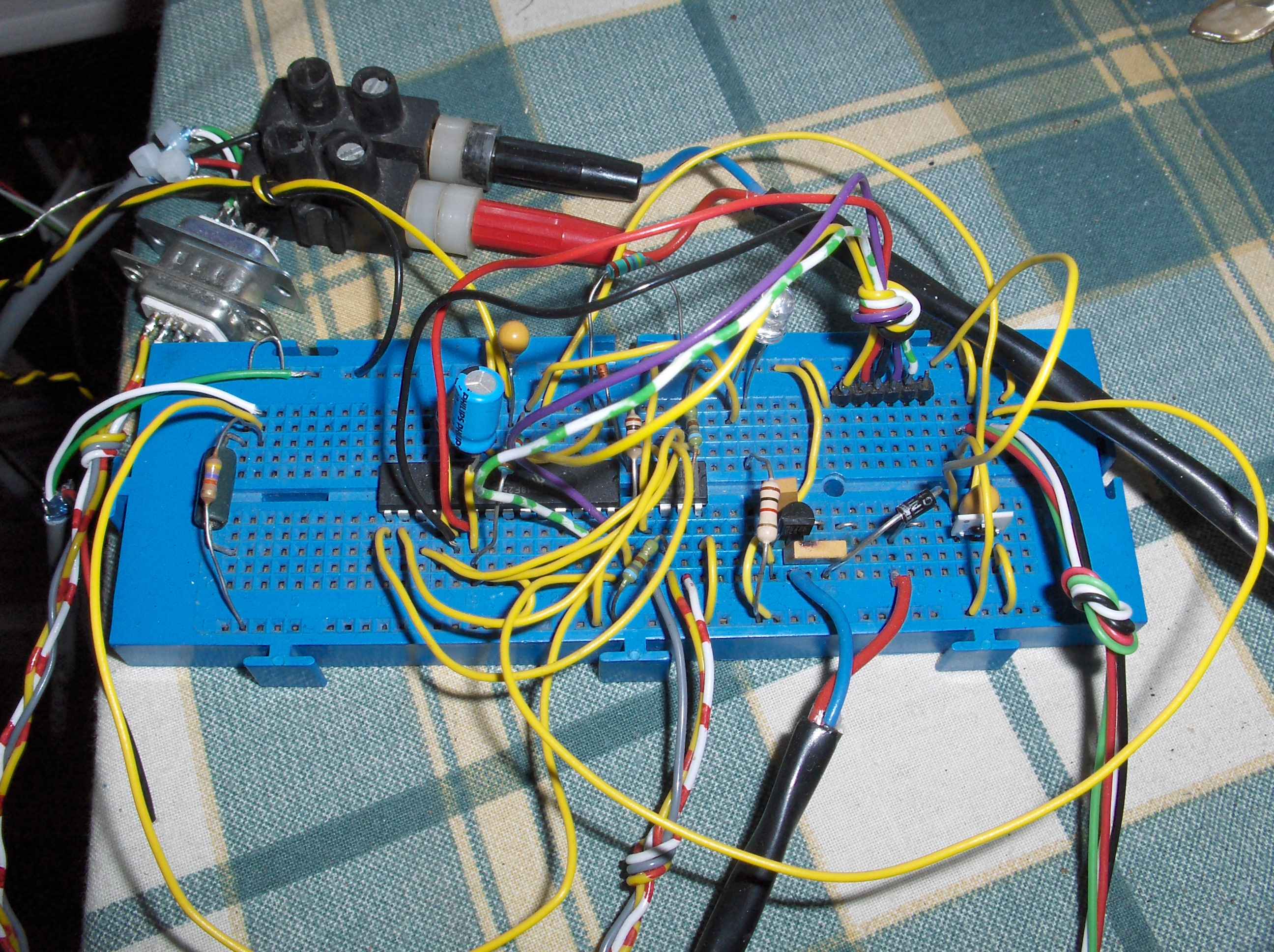
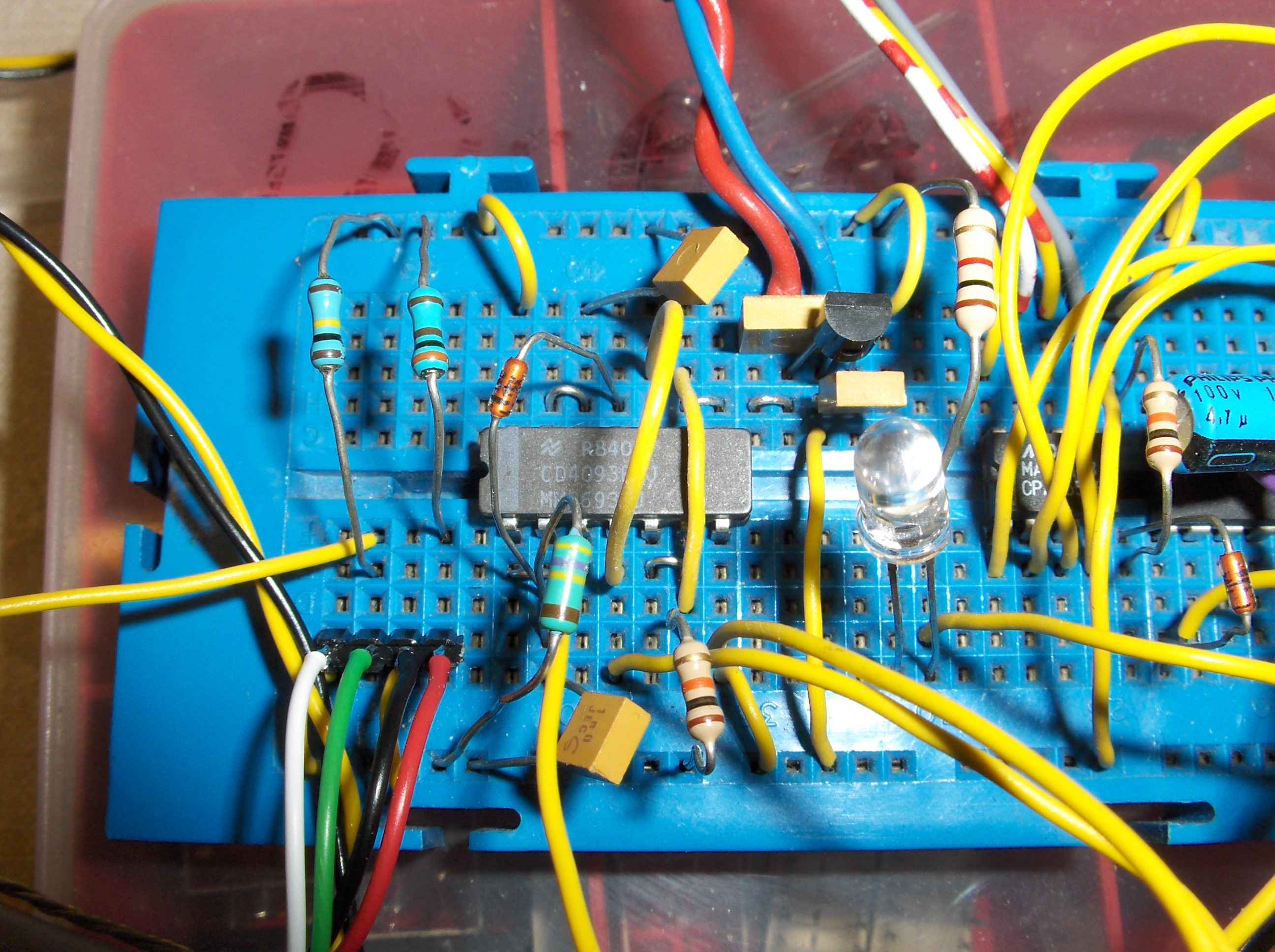
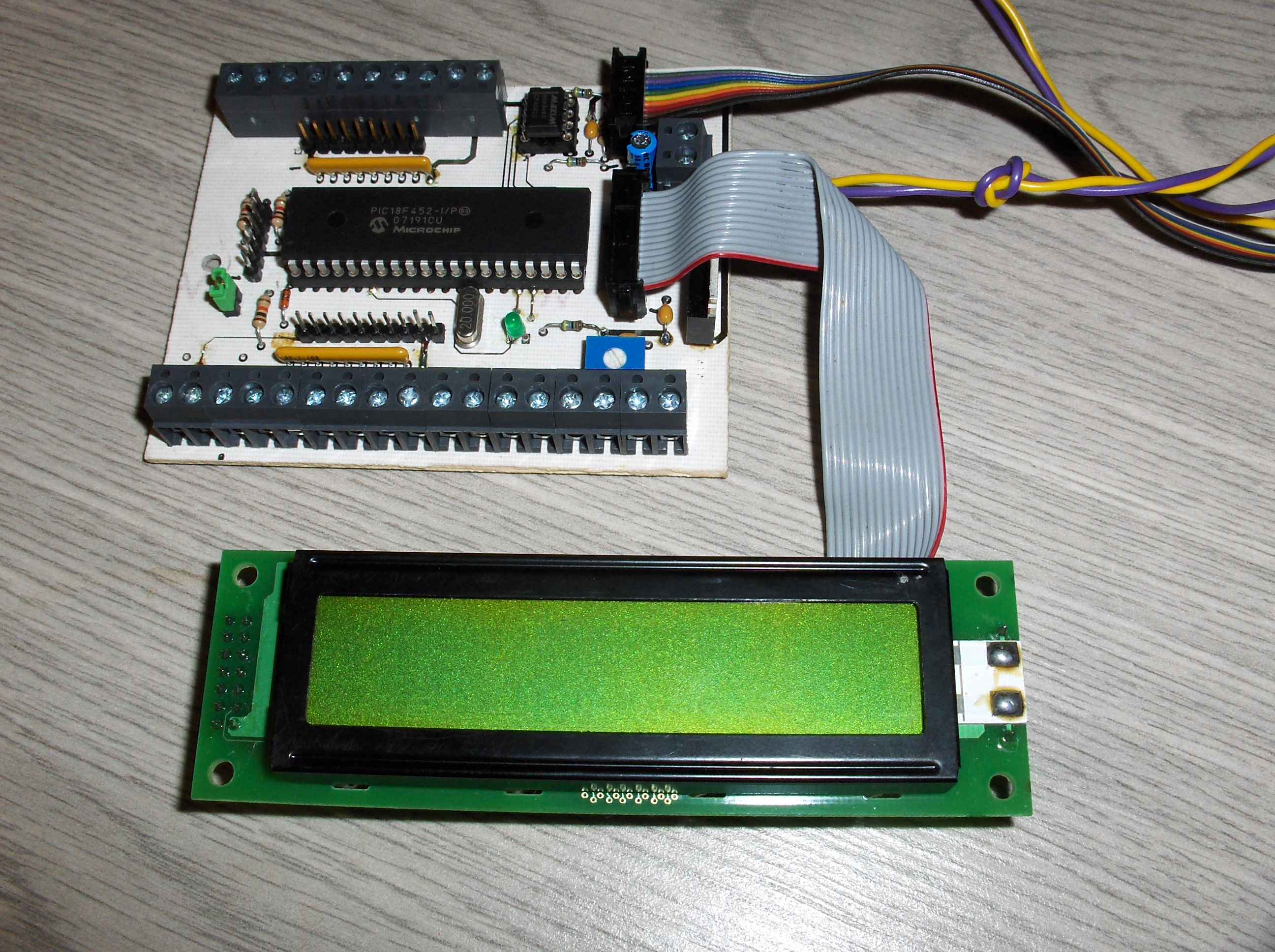
this the interim prototype of the Pulse Counter Processor it is a PIC18F252. This prototype has a temperature and RH sensor. But as yet the hard ware for the mains Voltage and urrent is still not added. Though the s/w is written and tested ok so far.
This is it working for the first few months of 2010 while I had to get on with lots of other things. Car repairs PV Reg repairs etc etc at least like this it did allowed me to collect data.
After a Change of Processor a PCB design and a total rewrite of the software I produced a Generic Controler. 8 ADC inputs 4 Digit Open Drain O/P 4 Counter inputs. programable scaling of ADC. During this I increased the coms speed of the whole 485 coms system from 2400 to 38000Baud
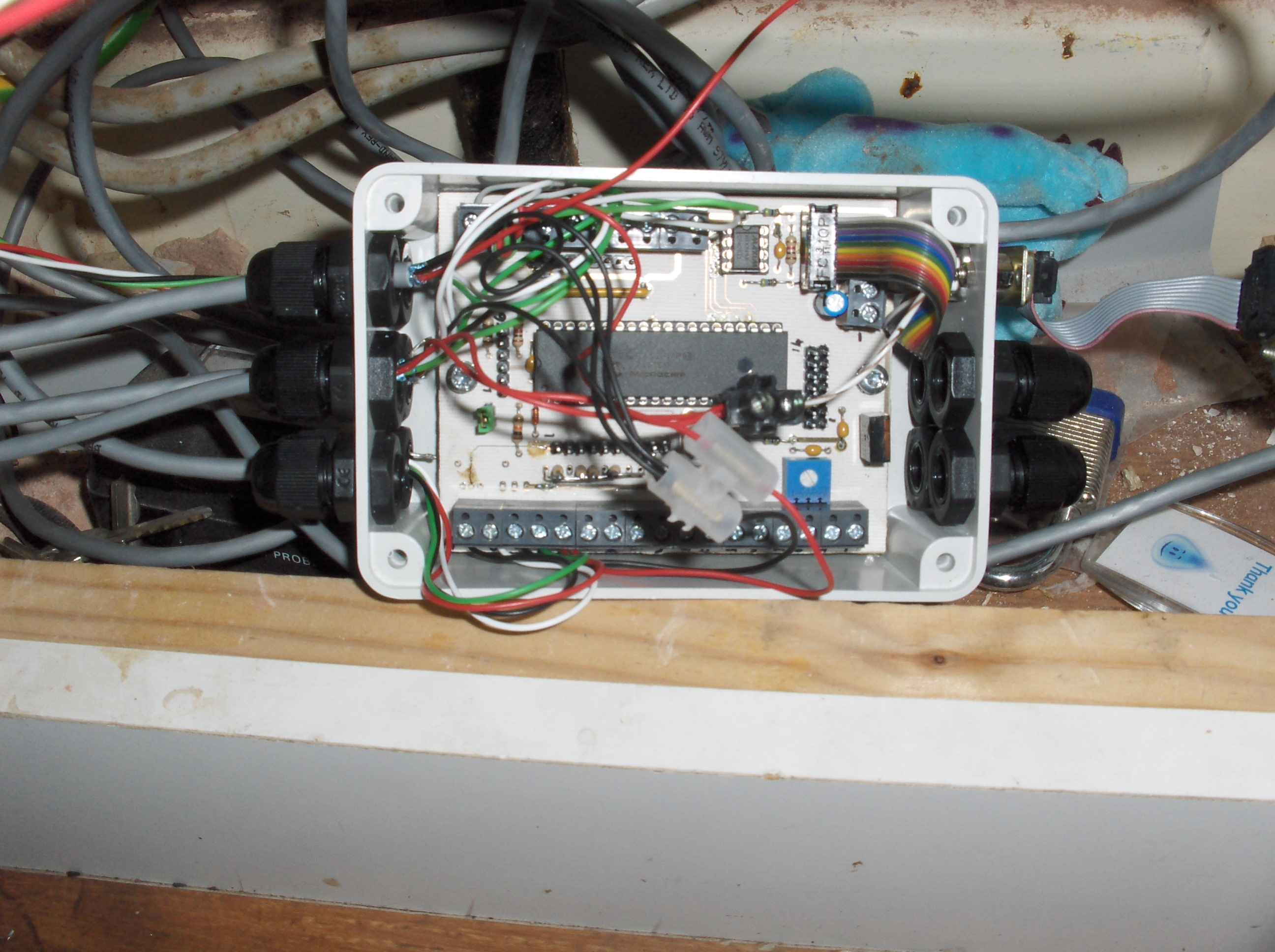
Finished jobby in a box. Yes good god I actually finished this one properly. I have deployed several of these now one does this job another monitors and controls the freezer temperatures another the workshop teperature humidity and heating control. I havejobs for more when I make them