New PV Az Drive Feedback

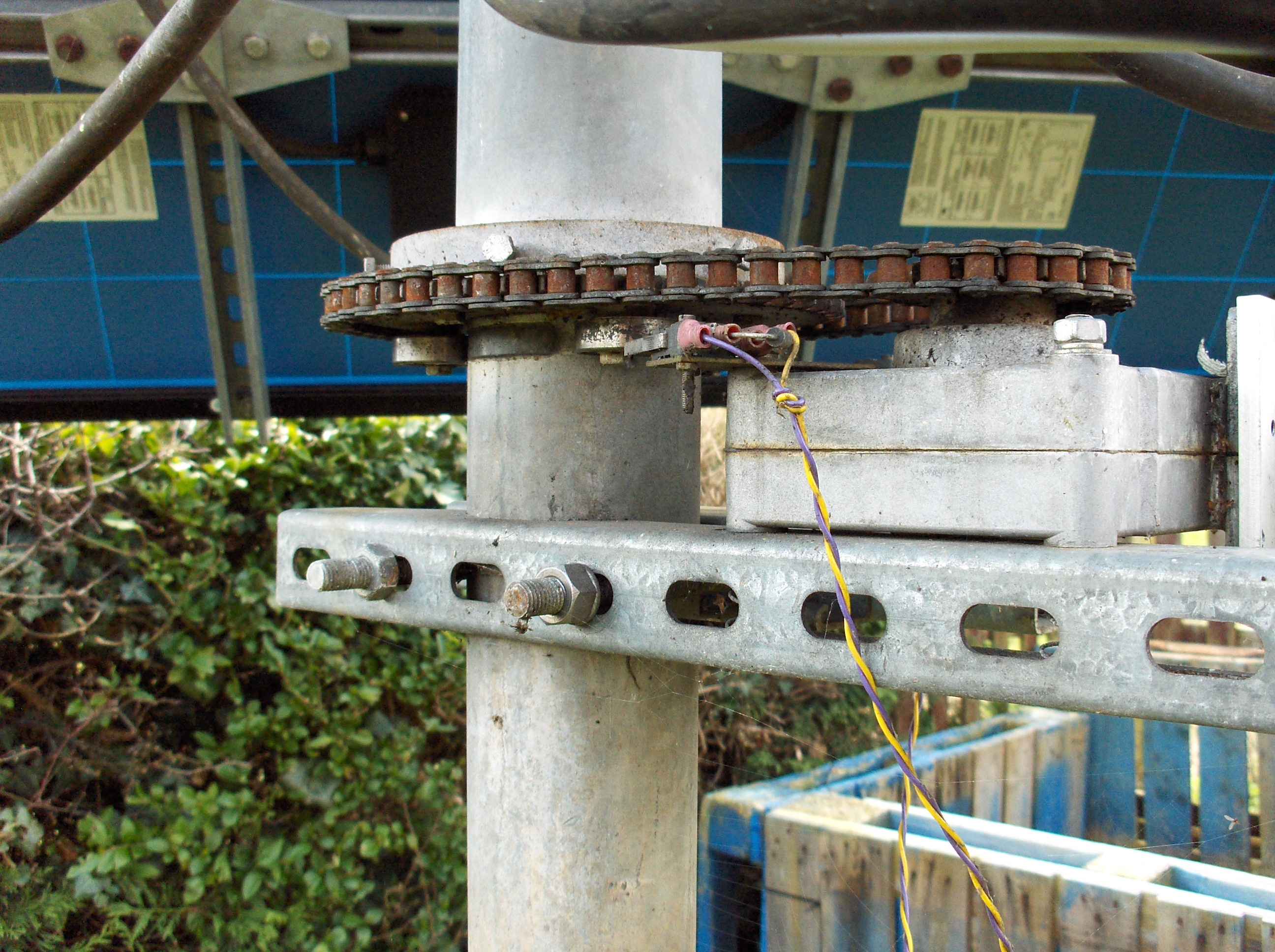
The original position feedback system used a hall effect device on the output shaft of the motor/gearbox assembley. This gave 4 pulses per revolution of the gearbox output, and drove a worm and gear that had a 60:1 ratio. This in turn drive a sproket and chain with a ration of 2.5:1 giving a total number of pulses per PV revolution of 600. This limited accuracy (about 0.6 Deg/Pulse) of the Az tracking system and needed to be improved.
The original motor protection left a little to de desired too... Astounding it actually worked like this for about 2-3 years before it finaly decided enough was enough. Even then it only ned a clean up.
Moving the pulse detection to the actual motor armature is the ideal solution. the Motor/Gearbox assembley has an unknown but significant reduction ratio in the order of 100:1 this give a total of about 60,000 pulses per PV revolution. and about 6E-3 Deg/Pulse.
As you can see I ground out a channel in the one Field magnet half so I could lockite a very small opto tx/rx module in there. I then Polished the surface of one armature pole and blacked the rest with indelable pen.
In order to get good square pulse from the opto tx/rx it required some signal conditioning. This is the rough draft of the final cct. there are still some value to be chosen.
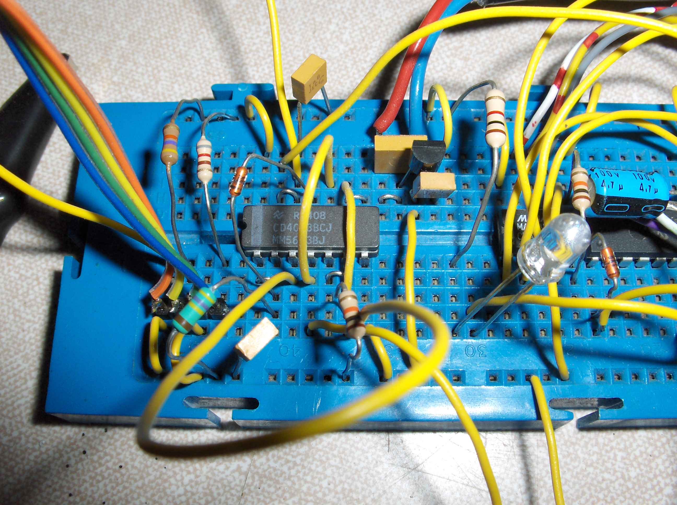
The prototype of the cct...
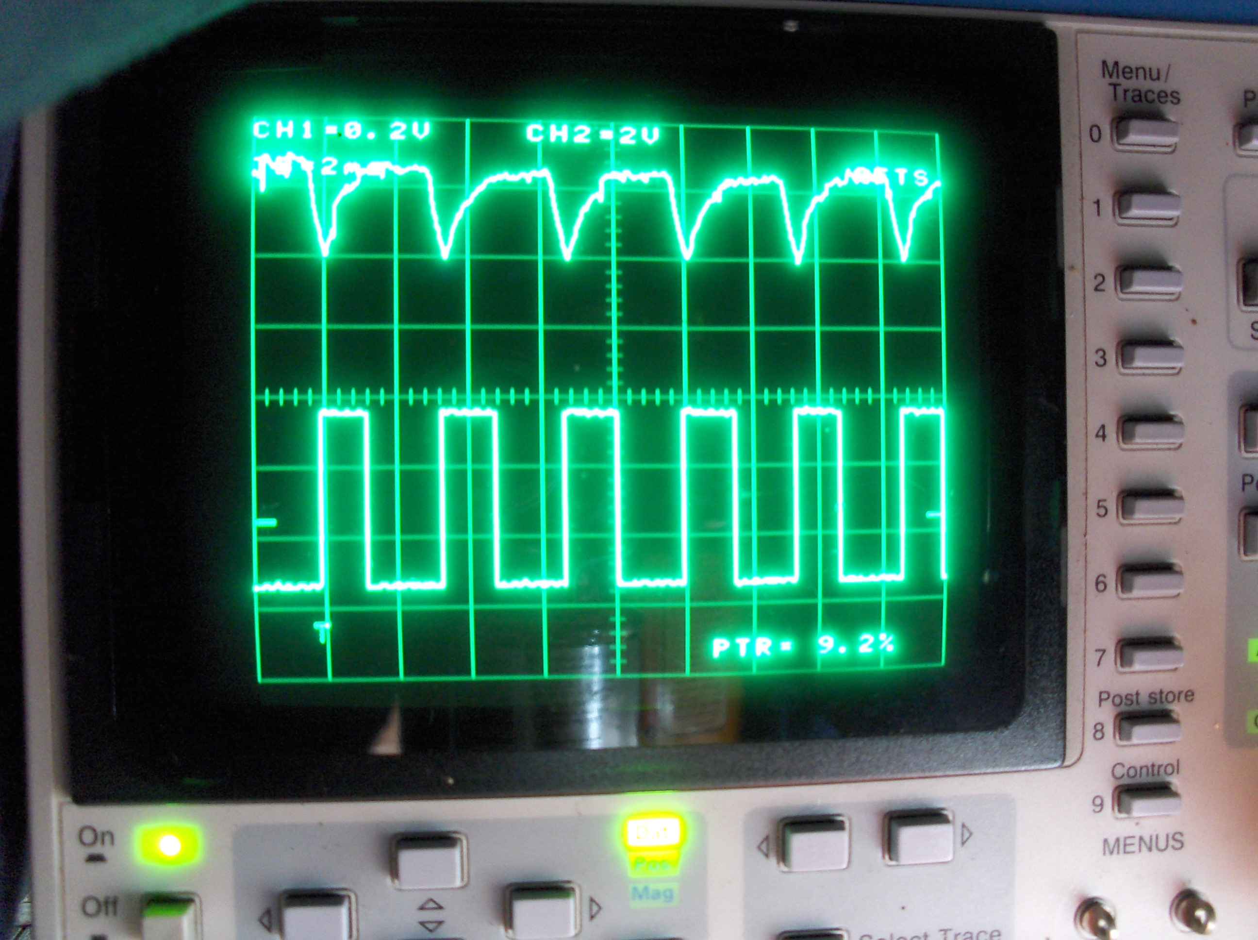
The input and output pulses fro the signal conditioner.
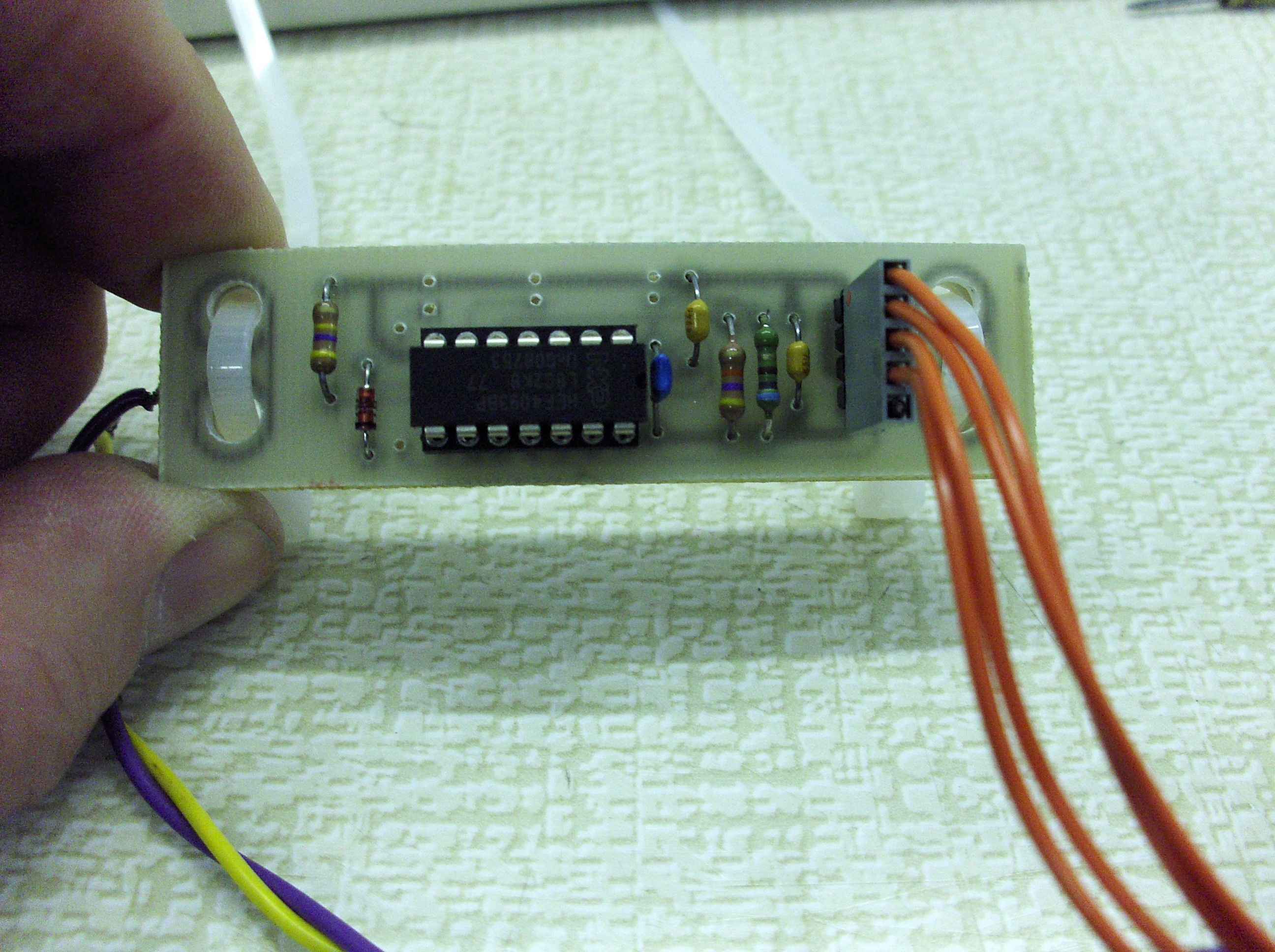
I was able to use as the final circuit design and PCB was identical to power monitor electric meter disc rotation detector. With some minor component value adjustments
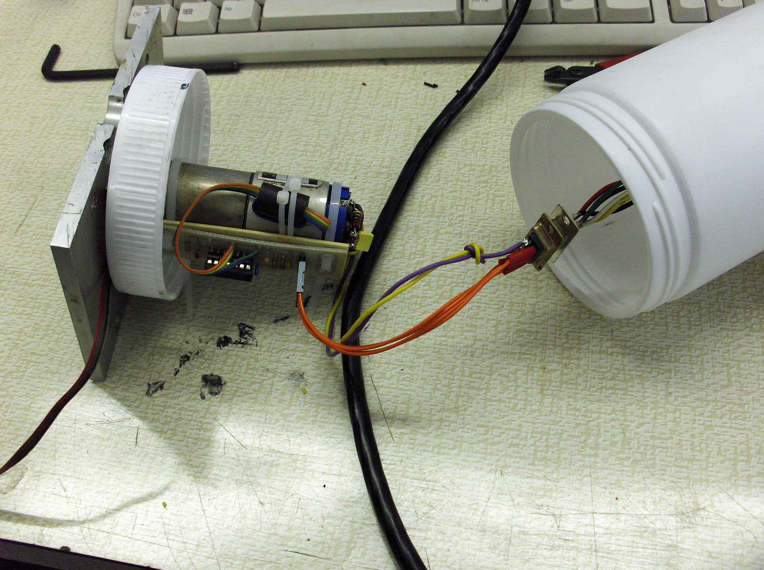
The tesco bags had to go too... So I decided to go for the Vanish wishing power container instead. It sounds nearly as bad bt actually looks the part and really has worked well keeping the motor protected through some really horrid weather.
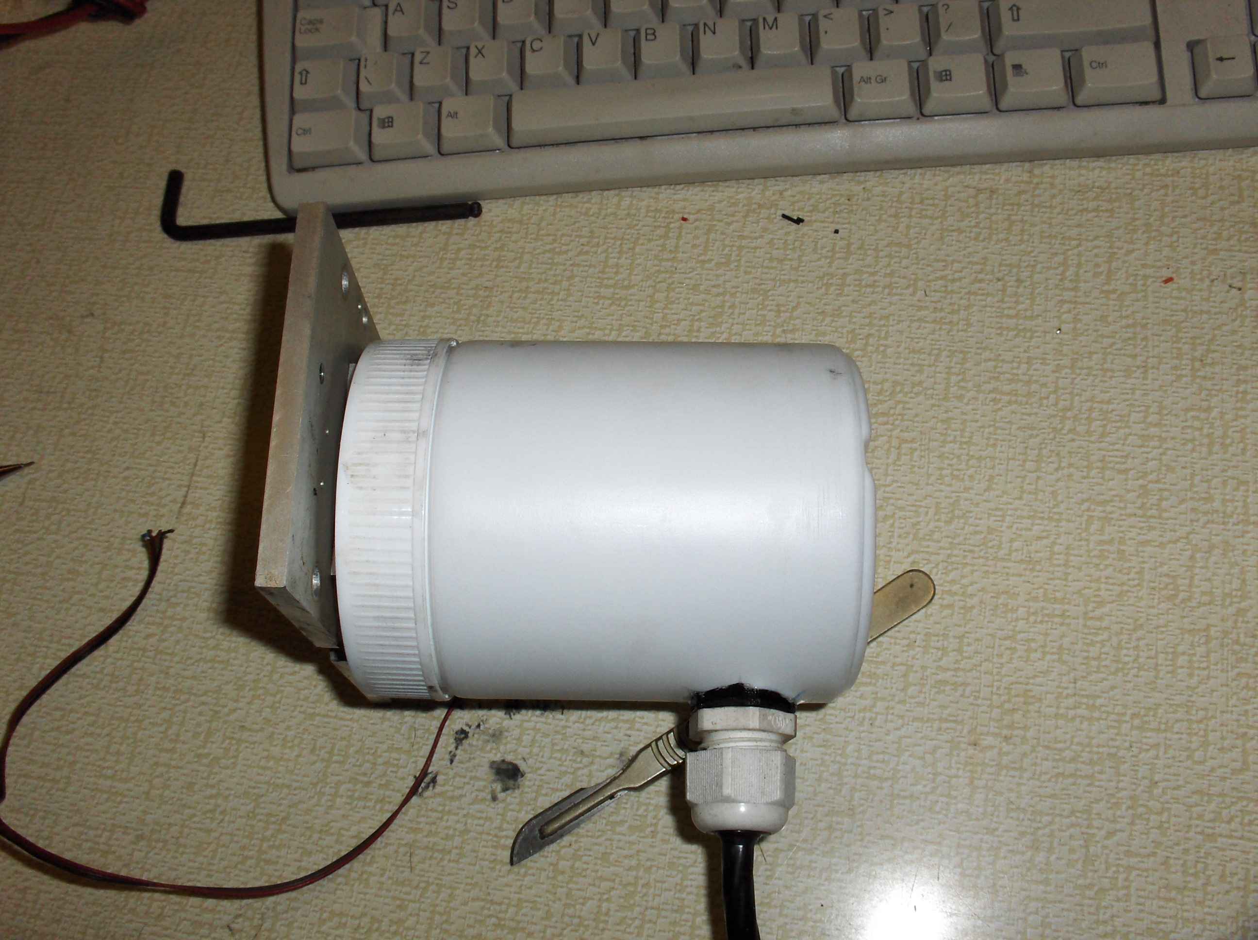
This is the assembled drive and feedback board in it's new housing. (the bit of cable pokeing out to the left is the old feedback hall effect sensor cable.
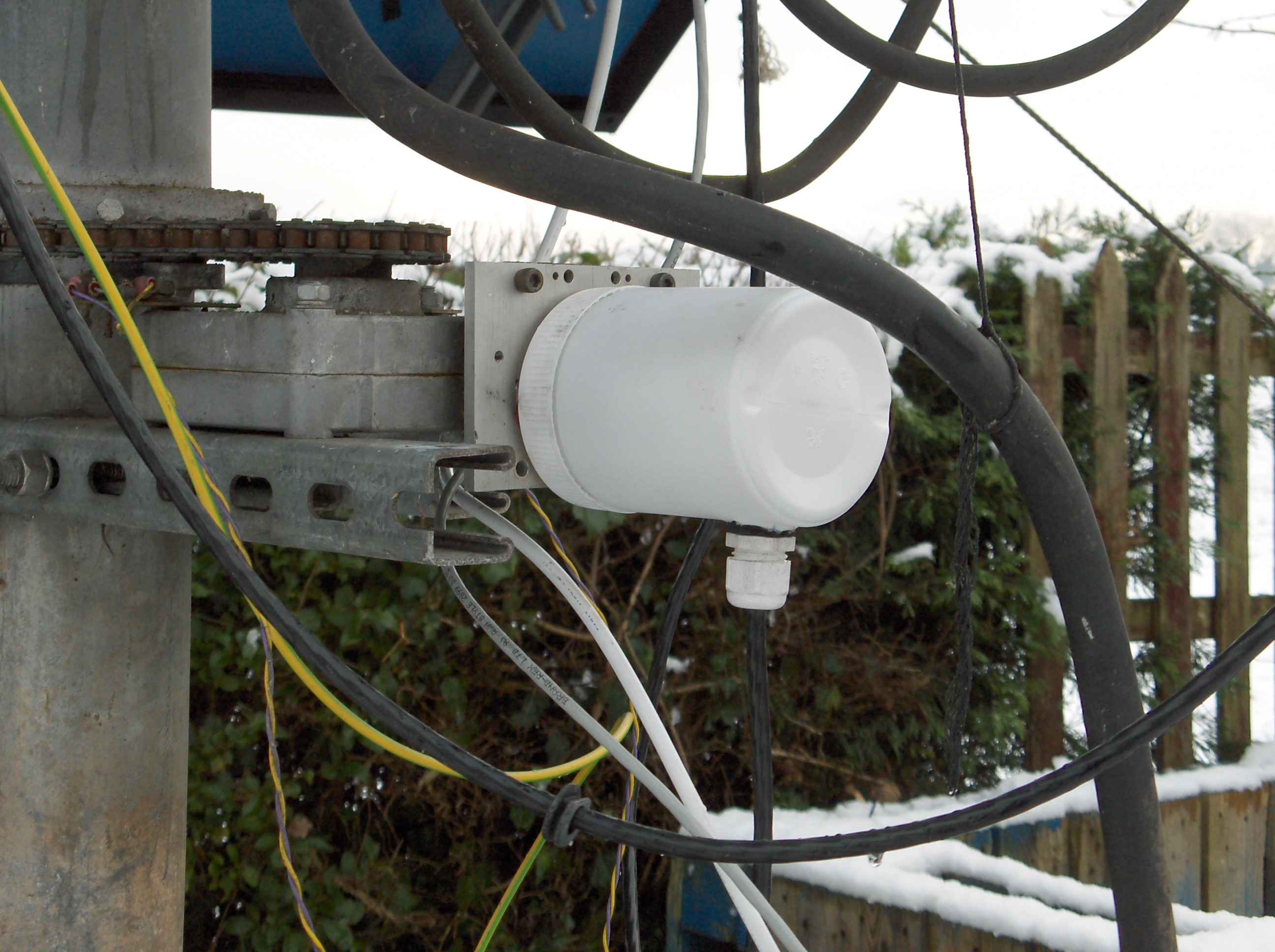
The final assembly installed and working. Hell it even looks the part.
The Limit switches are still exposed to the elements so guess I will have to rethink how they are mounted next...