S.M.P.S. are smaller and lighter and more efficient. They can also be produced to cover a wide range of input voltage without tapping changes, but their main feature is their efficiency.
The switch mode power supply is very different from is analogue equivalent. In effect an analogue PS varies the impedance of the PASS TRANSISTOR in order to maintain a constant O/P voltage. The more current you draw from your PS the more you have to bias your pass transistor on to lower its impedance to allow the extra current to flow and maintain the O/P voltage. The pass transistor continually passes the load current and continually drops the voltage difference between the reservoir capacitors (I/P) and the load (O/P) voltage. Thus is continually dissipating quite large amounts of power. For example a: -:
The SMPS varies the duty cycle (ratio of the on/off cycle) of the SWITCHING TRANSISTOR this is called Pulse Width Modulation. This transistor is either in SATURATION passing current with little volt drop or OFF not passing current and with the full supply voltage across it. The first case dissipates a little power, the volt drop across a saturated bipolar transistor = 0.2-0.3V the current say about 1 amp in a 240 W power supply [they switch at mains voltage i.e. mains R.M.S. x 1.414] giving dissipation of roughly 0.3 W the second case dissipates no power. The switching transistor will take a finite time to change from off condition to the on and from on condition to the off and during this transition the switching transistor will be passing current and dropping voltage i.e. dissipating power. If the switching times are kept high we can ignore these losses. So you can see the switching transistor will dissipate very little power.
Other losses in the power supplies i.e. rectification losses are about the same in both systems but never the less significant improvements in PS efficiency can be made by using SMPS.
The key components in a SMPS are the INDUCTOR, SWITCHING TRANSISTOR, FLYWHEEL DIODE and PWM (Pulse Width Modulation) generator.
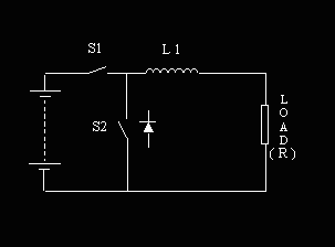
Take a look at the following circuit :

If you close switch S1 with S2 open, current starts to flow through L1 on through the load and back to the battery. This current increases in a roughly linear manner with time until S1 is opened or L1 reaches saturation. The rate of increase is dependant on the inductance and supply voltage
If you then simultaneously open S1 an close S2 current ceases to flow from the battery through L1 and the load. The magnetic field built up around L1 begins to collapse, this induces a current in L1 and the load in the same direction as the original current the circuit being completed by S2. This current decays in a roughly linearly manner until the field is completely collapsed or S1 and S2 are switched again.
If you now alternate S1 and S2 conditions with a duty cycle and frequency such that the current flow is roughly maintained, you have will have a constant (ish) current, which with constant load ,will give you a constant voltage. This is the beginnings of a SMPS.
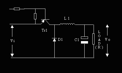
S2 can be replaced with a diode D1 and S1 with a switching transistor Tr1. We
should now assign some values to the components etc. in this circuit and
build and try it.

If we also assume a constant input Vi and output voltage Vo (makes the math easy). Using these values if we switch Tr1 on for 10uS the change in current in the inductor and load should be : -
Rearranging (1)
di = (Vi-Vo/L) x dt = (12 - 6/400E-6) x 10E-6 = 0.150A... So Don't believe me
Then if we switch Tr1 off for 10uS the change in current should be : -
di = (Vo/L) x dt = (6/400E-6) x 10E-6 = 0.150 A…
Note: This is calculating the ripple current NOT the load current.
There is more to come when I get round to it Honest Guv... 01/01/2006